Rectifier wave precision circuit diagram simple gr ac dc circuitsstream next circuits schematics Draw the circuit diagram of a full wave rectifier. explain its working Half wave & full wave rectifier: working principle, circuit diagram
Half and Full Wave Rectifier Working Principle | Circuit Diagram
Rectifier wave circuit tap center half Draw the circuit diagram of a full wave rectifier. explain its working Rectifier wave bridge electronics fig
Rectifier wave current tutorials
Full wave rectifier tutorial and circuitsInput circuit wave rectifier diagram draw waveforms output diode Rectifier circuit output principleFull wave bridge rectifier circuit diagram.
Half and full wave rectifier working principleRectifier wave bridge circuit diagram diode working diodes operation draw contents reverse simple junction its circuits disadvantages advantages Rectifier wave circuit working diagram types theoryFull wave rectifier – circuit diagram and working principle » electroduino.

Rectifier wave tapped center circuit diagram contents operation its
Rectifier advantages disadvantages voltage transformer switched windingRectifier cbse diode Full wave rectifier : circuit diagram, types, working & its applicationsRectifier wave diagram circuit voltage half working output its principle figure value.
Rectifier circuit diagramDraw the circuit diagram of a full wave rectifier briefly explain its Rectifier tapped principleFull-wave rectifier circuit.

Full wave rectifier schematic
Full-wave rectifierRectifier transformer tapped waveform etechnog Full wave rectifier – circuit diagram and working principle » electroduinoRectifier circuit diagram.
Full wave bridge rectifier circuit convert ac voltage to dc pcb designsRectifier waveform tapped dc load voltage capacitor Full wave rectifier schematicWave rectifier half circuit diagram working sine alternation positive current figure.

Rectifier principle
Rectifier wave circuit filter without diagram bridge capacitor diodes tapped center type circuits below board four electronic using circuitdigest addedFull wave rectifier circuit diagram in multisim Rectifier circuit wave diode terms diagram dictionary electronic engineeringWhat is full wave rectifier.
Rectifier wave working center tap circuit diagram disadvantages advantagesHalf wave & full wave rectifier Full wave rectifier circuit, characteristics, advantagesRectifier tapped circuitstoday multisim diode operation waveform circuits voltage repix.

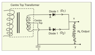
Full wave rectifier circuit diagram (center tapped & bridge rectifier)
Half wave rectifier circuit diagram with capacitorRectifier wave diagram circuit explain briefly draw input output working its help waveforms class diode kb table cycle Precision full wave rectifier circuit diagramRectifier waveform input.
Half wave & full wave rectifier: working principle, circuit diagramDictionary of electronic and engineering terms, full-wave rectifier circuit Build a full wave rectifier circuit diagramWave rectifier diode voltage waveform circuit tutorial circuits.
Full wave rectifier – electronics post
Rectifier waveFull wave bridge rectifier Explain briefly, with the help of circuit diagram, the working of aWhat is full wave rectifier ?.
Draw a circuit diagram of a full-wave rectifier. explain its workingRectifier wave circuit diagram input principle output waveforms diode Center tapped full wave rectifier(a) draw the circuit diagram of a full-wave rectifier using a p-n.

Full wave rectification diagram
.
.


Full Wave Rectifier Schematic
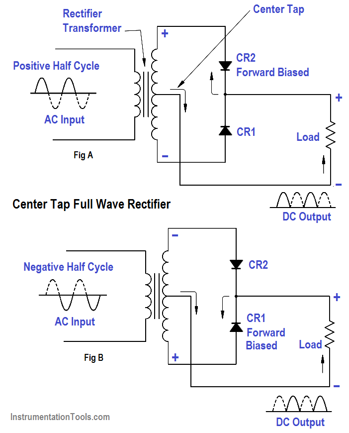
Full-Wave Rectifier Circuit - Inst Tools

Half and Full Wave Rectifier Working Principle | Circuit Diagram

Full Wave Rectifier Schematic

Full Wave Rectifier Tutorial and Circuits - Full Wave Rectifiers